 Power Cable
 General Power Cable
 XLPE insulated power cable for rated voltage up to and including 35kV
 XLPE insulated anti-termite and anti-rat environmental power cable for rated voltage up to & including 35kV
 XLPE insulated waterproof power cable for rated voltage up to and including 35KV
 Silicon rubber insulated power cable
 Fluoroplastics insulated heat resistant power cable
 NBR Flexible Power Cable
 Power cable with concentric conductor
 Special cable for frequency converter
 Metal shielded power cable
 Oxygen barrier and high flame retardant power cable
 EPR insulated power cable for rated voltage up to and including 35kV
 Plastic insulated and sheathed branch cable of rated voltage up to and including 0.6/1kV
 0.6/1kV PVC insulated power cable
 0.6/1kV polyolefin insulated power cable
 0.6/1kV flame retardant B1 class power cable
 0.6/1kV flame retardant B2 class power cable
 Aluminium Alloy Power Cable
 Special Explosion Proof Cable
 8.7/15KV And Below Medium Voltage Special Explosion-Proof Cable
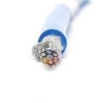 450/750V and below Special Explosion-Proof Control cable
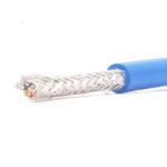 300/500V Special Explosion-Proof Computer Cable
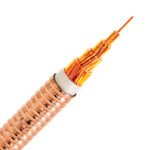 Mineral Insulated Fire-proof Cable
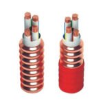 Metal sheathed inorganic mineral insulated cable
 Copper core mineral insulated flexible fire proof cable for wiring rated voltage upto and including 0.6/1kV
 Industrial Cable & Civil Cable
 Industrial Control Cable
 XLPE insulated and sheathed control cable
 PVC insulated and sheathed control cable
 Polyolefin insulated and sheathed control cable
 NBR insulated and sheathed flexible control cable
 Thermoplastic elastomer insulated and sheathed flexible control cable
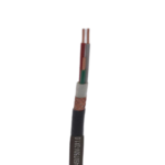 Fluoroplastic insulated high temperature resistant control cable
 Silicon rubber insulated heat resistant control cable
 450/750V flame retardant B1 level control cable
 Thermocouple Compensation Cable
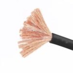 Rubber Sheathed Cable for General Purpose
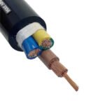 Rubber insulated flexible cord and cable
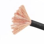 Welding Cable
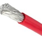 Flexible cables & cords for electric motors leads
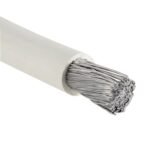 90℃ Flexible Cable(Wire) for Motor Connection
 125℃ & 150℃ Flexible Cable(Wire) for Motor Winding Connection
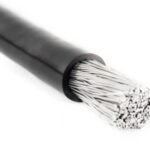 180℃ Flexible Cable(Wire) for Motor Winding Connection
 Movable Flat Cable
 Silicon rubber Insulated flat cable
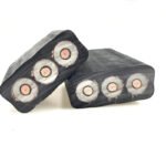 EPR Insulated flat cable
 NBR insulated flat cable
 Heat-resistent Fire-proof Cable (Fire Protection Type)
 Fireproof cable for high temperature uses
 Automatic Control Temperature Heating Cable
 Automatic-control-temperature Heating Cable
 Low temperature, Middle temperature, High temperature series
 The series of excessively-long cable
 Maintaining temperature for duct
 The Comprehensive Application of Automatically-Restricted-Temperature Electric-Heating Belt into the Household Electric Equipment
 The Component of the explosion-proof heating belt andaccessories of installation
 Installation Cable Residential Wire
 PVC insulated cable (wire)
 Low smoke halogen free flame retardant and environmental installation wire
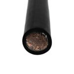 Cable for Railway Vehicle & Metro
 EPR rubber insulated cable for railway vehicles & metro
 XLPO insulated cable for railway vehicies & metro
 NR+SBR insulated cable for railway vehicles & metro
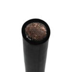 CSP rubber insulated cable for raiiway vehicles
 Communication Cable
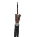 Instrumentation Cable
 PE or XLPE insulated computer cable
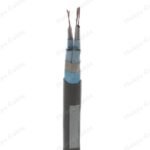 PVC insulated computer cable
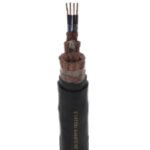 Fluoroplastics insulated computer cable
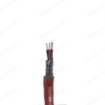 Silicone rubber insulated computer cable
 PAS/BS5308 Part1 Type 1&2
 PAS/BS5308 Part2 Type 1&2
 Fire Resistant Instrumention Cable
 Radio Frequency Cable
 EIA RS485 RS232/RS422
 Bus Cable
 LAN/ Network Cable
 Fiber Optic Cable
 Mining Cable
 Flexible Coalcutter Cables for Rated Voltage up to and Including 1.9/3.3kV
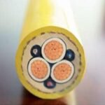 Flexible Strengthened Coalcutter Cables With Monitoring Core and Screen for Rated Voltage of 0.66/1.14kV
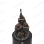 Flexible Coalcutter Cables With Metallic Screen For rated Voltage up to and Including 1.9/3.3kV
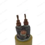 Flexible Rubber-Sheathed Cables for Rated Voltage up to and Including 0.66/1.14kV
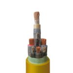 LSZH Flexible Rubber-Sheathed Cables for Rated Voltage up to and including 0.66/1.14kV
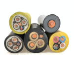 Drill Cables with Rated Voltage of 0.3/0.5kV for Mining Purpose
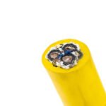 Flexible Rubber-Sheathed Light-Duty Cables for Mining Purpose
 PVC Insulated Flame Retardant Mining Power Cable
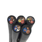 XLPE Insulated Mining Power Cable
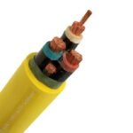 Flame-Retardant Mining Control Cable
 Reeling Cable &Trailing Cable
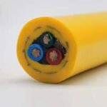 Low voltage reeling cable
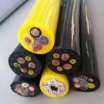 Spreader rolling cable
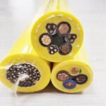 Spreader basket cable
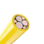 Shipboard Cable & Marine Engineering
 Shipyard Cable & Marine Cable & Offshore Cable
 Marine Power Cable
 EPR insulated shipboard power cable for rated voltage from 3.6/6 to 18/30kV
 XLPE insulated shipboard power cable for rated voltage from 3.6/6 to 18/30kV
 EPR insulated shipboard power cable rated voltage up to and including 0.6/1kV
 EPR insulated Fire-Resisting shipboard power cable rated voltage up to and including 0.6/1kV
 Silicon Rubber Fire-Resisting insulated shipboard power cable for rated voltage up to and including 0.6/1kV
 XLPE insulated shipboard power cable for rated voltage up to and including 0.6/1kV
 Marine Control Cable
 XLPE insulated shipboard Control cable rated voltage up to and including 250V
 XLPE insulated Fire-Resisting shipboard Control cable rated voltage up to and including 250V
 EPR insulated Fire-Resisting shipboard Control cable rated votage up to and including 250V
 Marine Instrumentation cable & Communication cable
 XLPE insulated Fire-Resisting shipboard telecommunication cable for rated voltage up to and including 250V
 EPR insulated shipboard telecommunication cable for rated voltage up to and including 250V
 EPR insulated Fire-Resisting shipboard telecommunication cable for rated voltage up to and including 250V
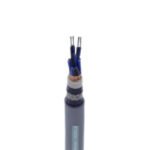 Naval Ship Cable
 Naval Ship Power Cable
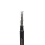 XLPE insulated naval ship power cable for rated voltage up to and including 0.6/1kV
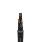 EPR insulated naval ship power cable for rated voltage up to and including 0.6/1kV
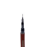 Naval Ship Control Cable
 EPR insulated naval ship control cable for rated voltage up to and including 600V
 Naval Ship Instrumentation cable & Communication cable
 XLPE insulated naval ship telecommunication cable for rated Voltage up to and including 300V
 Low-smoke halogen-free flame-retardant light thin-walled telecommunication cable for naval ships
 Watertight Cable for Naval Ship
 Watertight Power Cable
 XLPE insulated naval ship water-tightness power cable for rated voltage up and including 0.6/1kV
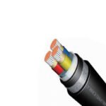 Watertight Control Cable
 XLPE insulated naval ship water-tightness control cable for rated voltage up to and including 600V
 XLPE insulated naval ship water-tightness fire-resistance control cable for rated voltage up to and including 600V
 EPR insulated naval ship water-tightness control cable for rated voltage up to and including 600V
 EPR insulated naval ship water-tightness fire-resistance control cable for rated voltage up to and including 600V
 XLPE insulated naval ship water-tightness fire-resistant telecommunication cable for rated voltage up to and including 300V
 EPR insulated naval ship water-tightness telecommunication cable for rated voltage up to and including 300V
 EPR insulated naval ship water-tightness fire-resistant telecommunication cable for rated voltage and including 300V
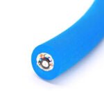 Aramid fiber strength signal cable for naval ships
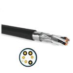 Low smoke digital communication LAN cable
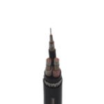 LV Power Cable for Oil Platform
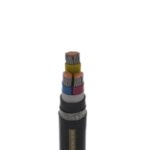 Power cable for offshore oil platform with rated voltage up to and including 0.6/1 kV
 Fire-Resisting power cable for offshore oil platform with rated voltage up to and including 0.6/1kV
 Telecommunication cable for offshore oil platform with rated voltage up to and including 150/250V
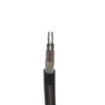 EPR insulated power cable for offshore oil platform with rated voltage from 3.6/6 to 18/30kV
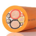 New Energy Cable
 Wind Power Generation Cable
 Wind Power mobile cold-proof anti-reversing Control cable
 Solar/Photovoltaic Cable
 Solar Cable TUV 2PFG 1169
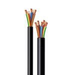 EV Charging Cable EN50620
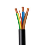 EV Cable H05BZ5-F & H07BZ5-F
 Special Cable
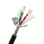 Special Industrial Cable
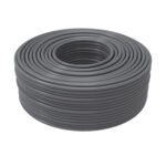 XT Series Phase-Stable Low-Loss Coaxial Cable
 SFF Series Solid PTFE Insulated RF Coaxial Cable
 SYV Series Solid PE Insulated RF Coaxial Cable
 Field-Use XTFUP-1004x2x24A Type Special Ethernet Cable
 Field-Use DVl Video Transmission Cable
 Field-Use AGTRQ Series Special Flexible Wire
 Field-Use XTRT Series Special Flexible Power Cable
 Field-Use XERJ Series Abrasion-Resistant Flexible Power Cable
 Metal Braid Series A: XTP Series EMl Shielding Sleeve
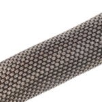 Metal Braid Series B: XTP Series Grounding Cable
 Field-Use Computer Cable
 Field-Use Special Control Cable
 Aeropace/Aviation Cable
 XTA1 Series High-Performance Transmission wire for Aerospace
 XTA2 Series High-Performance Transmission wire for aviation
 XTA3 Series High-Performance Transmission wire for aviation
 XTAX Series High-Performance Ultra-Flexible Transmission wire for aviation
 XTE Series High-Temperature Resistant Wire for aviation
 XTER Series High-Temperature Resistant Wire for aviation
 XTEX Series High-Temperature Resistant Ultra-Flexible Wire for aviation
 AFR-250 Series PTFE Film-Wrapped Insulated Installation Wire for aviation
 AF Series Fluorinated Ethylene Propylene (FEP) Insulated Wire for aviation
 AF Series Soluble Polytetrafluoroethylene (PFA) Insulated Wire for aviation
 XTCMC Large-Cross-Section Flexible Wire for aviation
 C55 Series Aerospace-Grade Crosslinked Ethylene-Tetrafluoroethylene Copolymer (XETFE) single-Layer Insulated Wire
 XETFE-Insulated 1553B Data Bus Cable for aerospace
 Model C772451664 Aerospace-Grade 1553B Data Bus Cable
 Aviation-Grade 100Ω Special Category 5e Cable
 Model THWFPF-110 1x4x24A 1394b Data Bus Cable for aerospace
")
Field-Use XERJ Series Abrasion-Resistant Flexible Power Cable
Overview
XERJ series special soft power cable is divided into power cable and control power cable, power cable is suitable for power transmission; control power cable is suitable for instrumentation and control of electrical equipment.
The power supply cable is suitable for power transmission; the control power cable is suitable for the control of instrumentation and electrical equipment. The product adopts cross-linked soft material insulation, special wear-resistant elastomer material sheath, with excellent electrical performance, anti-aging, low temperature (-45 ℃) oil, moisture and acid and alkali erosion resistance and other characteristics. The cable has soft structure, high mechanical strength, high resistance, tear resistance, and is suitable for energy and information transmission of power and electrical equipment under special environment in the field.
Executive standard
Q/XTHY 05-2022 Special soft power cable
Characteristics
Rated working voltage: 450/750V and below.
Cable working temperature:-45℃~+90℃.
Minimum bending radius of the cable when fixed laying: 4 times of the outer diameter of the cable.
Model and Name
XERJ:Cross-linked flexible material insulation, special abrasion-resistant elastomer sheathed special flexible power cable
XERJP:Cross-linked flexible material insulation, tinned copper wire shielding, special wear-resistant elastomer sheath special soft power cable
XERJ80:Cross-linked flexible material insulation, special wear-resistant elastomer jacket, tinned copper wire armored special soft power cable
Cable specification
Table 1 Power supply cable
| Core No. | Nominal Cross Section mm2 |
| 1 | 1.5~300 |
| 2 | 1.5~95 |
| 3 | 1.5~120 |
| 4 | 1.5~120 |
| 3+1 | 2.5~120 |
Table 2 Control Cable
| Core No. | Nominal Cross Section mm2 |
| 3,4 | 0.35 |
| 2~37 | 0.50 |
| 2~37 | 0.75 |
| 2~30 | 1.0 |
| 2~27 | 1.5 |
| 2~19 | 2.5 |
Main Properties
Conductor structure and conductor DC resistance are shown in Table 3
| Nominal Cross Section mm2 |
Cable Structure n/mm |
20℃ Max.Conductor Resistance Ω/KM |
| 0.35 | 20/0.15 | 57.8 |
| 0.50 | 16/0.20 | 40.1 |
| 0.75 | 24/0.20 | 26.7 |
| 1.0 | 32/0.20 | 20.0 |
| 1.5 | 48/0.20 | 13.7 |
| 2.5 | 77/0.20 | 8.21 |
| 4.0 | 126/0.20 | 5.09 |
| 6 | 189/0.20 | 3.39 |
| 10 | 324/0.20 | 1.95 |
| 16 | 513/0.20 | 1.24 |
| 25 | 798/0.20 | 0.795 |
| 35 | 1121/0.20 | 0.565 |
| 50 | 1593/0.20 | 0.393 |
| 70 | 560/0.40 | 0.277 |
| 95 | 756/0.40 | 0.210 |
| 120 | 960/0.40 | 0.164 |
| 150 | 1197/0.40 | 0.132 |
| 185 | 1444/0.40 | 0.108 |
| 240 | 1960/0.40 | 0.0817 |
| 300 | 2394/0.40 | 0.0654 |
Shielded power cables: braiding density not less than 85%.
Armored power cables: braiding density not less than 85%.
Finished product voltage withstand test: withstand frequency 3000V/5min high-voltage test does not break through.
Sheath low-temperature bending test: (-45±2)℃ conditions without cracking;
Thermal shock test: (135±2)℃ conditions without cracking.
Flame retardant performance: in line with GB/T18380.12-2008 requirements.
Product structure size, weight
……omit,
for more information,pls contact us